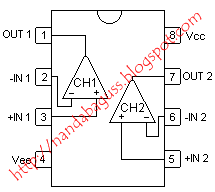
Persamaan Aice 4558
Contents • • • • • 5 Channel Graphic equalizer circuit using LA3600 This circuit 5 Channels 2 Octave Graphic Equaliser, easy to make equalizer, because using IC LA3600 (easy to use) For you who take an interest sound of music side may nobody strange Graphic Equalizer circuit, but, in you who is a novice, something will build this some group circuit gets into trouble moderately difficult, today I [ hair ] begs for to advise 5 Channels Graphic Equalizer circuit because it uses the integrated circuit LA3600. Be pillar equipment with the convenience that uses IC LA3600 just one only. As a result, can decorate the sound of music has every full frequency sound section already. You who are a novice and love the saving may don’t miss group this circuit. Cut at frequencies of 50Hz, 200HZ,800Hz,3.2kHz, and 10kHz. The supply voltage may be anything from +12V. Besides I still lead model PCB keep can give testimony try to build convenient increasingly.
PCB 5 Channels Graphic Equaliser by LA3600 10 Channel graphic equalizer circuit using LA3600 In addition to using the LA3600 IC, above was. We can also be designed was the 10 Channel Graphic equalizer circuit. By connection with the other IC LA3600. In the Figure is 10 channel equalizer circuit, which we have designed for the Q = 4. And uses the center frequency of the IC is interruption. Reason The first circuit be work at odd channels, including channels 1,3,5,7,9. As for second IC be doing in dual channel namely 2,4,6,8,10 channel.
PART NO: KIA278R05PI. MARKING: 278R05. TYPE: 4 TERMINAL 2A OUTPUT LOW DROP VOLTAGE REGULATOR. CONDITION: New parts. More details.
The strong point of this circuit be will reduce the interference between adjusting the volume the center frequencies similar is rise efficiency of the circuit And the sound quality is better than a general. 10 Channels Graphic Equalizer circuit by LA3600 IC Construction We assemble the components on the PCB properly and check soldering points must be tightly all points. Then we solder to the both PCB circuit are the volume and the equipment of IC join together successfully, as shown. When finished, we supply positive 12V circuit to be used immediately, without any adjustment. The PCB of this circuit Graphic equalizer circuit using op-amp 4558-LF353 This Graphic equalizer circuit using op-amp 4558-LF353 circuit 5 Channels 2 Octave Graphic Equaliser, easy to make equalizer, because using IC 4558 or LM1458 or LF353 (nice) If you are seeking Graphic Equalizer Circuit at can fine decorate the sound of music has full frequency sound section.
No Hope v1.65 (Compatible w/ update 10) Apr 8 2009 Full Version 18 comments. The mod works with update 10 and Soviet Assault. Happy hunting. How to install no hope mod world in conflict soviet assault mods.
As a result try out group this circuit before. May don’t be defeated. Cut at frequencies of 50Hz, 200HZ,800Hz,3.2kHz and 12kHz. Supply voltage may be anything from -15V GND -15V for IC 4558. Besides I still lead model PCB try build can be usable easy increasingly sir. PCB 5 Channels 2 Octave Graphic Equaliser by 4558 Graphic equalizer circuit using transistors BC548 This is graphic equalizer circuit using the transistor. We use it for controlling the.

For some kinds of audio frequency response is not smooth. The by the tone controls, may not work well. Because the bandwidth is too wide. The audio system requires the use of equalizer circuit with a narrow bandwidth, and to into frequency bands increased to 5 channels or more. It can specific actions required frequency bands. Transistors Graphic equalizer circuit The equalizer circuit can adjust the frequency to 5 channel is 60 Hz, 100 Hz, 1 kHz, 3 kHz and 12 kHz.
When we enter an input signal to through C1 to the positioning pin 1 of VR1-VR5. If we adjust the VR comes to the position of a signal pin will go to where both leads of the VR is going through a lot this signal – a low of each channel. The frequency of each channel is determined by the R1-R8, and C2-C9. And then, the signal will pass filter for each channel will be combined coupling d through C10 to expand with the Q1 and Q2. Which Commonwealth model for circuit E Foster limits the expansion of output pins of Q2 via C13 C into the output signal.
Next, signals and the other part is fed back via R12 to enter a location pins 3 of the VR1-VR5. Then we adjust VR through this to the phase opposite and will cancel the input signal at that point.
This is the Cut. Implementation is very simple. Just pre-intermediate tone with the power amp. If the system is used in stereo, then build up to another set.